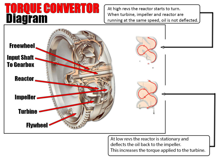
In a vehicle equipped with an automatic transmission, the torque converter plays a crucial role by linking the engine to the transmission’s gear train, which ultimately powers the wheels. Positioned between the engine’s flexplate and the transmission, the torque converter serves as a fluid coupling, allowing the engine to transfer power smoothly without a direct mechanical connection. This contrasts with a manual transmission, where a mechanical clutch performs a similar function, engaging and disengaging the engine from the transmission to allow gear changes.
Torque Converter
A torque converter is a fluid coupling device that functions similarly to a clutch, but instead of relying on direct mechanical engagement, it uses hydraulic pressure to transfer power.
Key Components of the Torque Converter
The torque converter consists of three primary components: the impeller, which is attached to the engine’s flywheel; the turbine, connected to the transmission’s input shaft; and the stator, positioned between them, featuring a one-way clutch known as a freewheel.
How the Torque Converter Works
As the engine accelerates, centrifugal force causes the hydraulic fluid within the converter to be propelled by the impeller’s vanes. This fluid transmits torque, or rotational force, to the turbine, driving the transmission.
The Role of the Stator
The stator plays a crucial role by redirecting the fluid flow back towards the impeller, increasing torque at low speeds. However, as the engine speed rises and more power is generated, the need for this torque multiplication diminishes, and the stator freewheels. At this point, the torque converter functions as a fluid flywheel, maintaining a connection between the engine and transmission.
Components in Action
The main components of a torque converter—the impeller, stator, and turbine—work together to manage the power flow from the engine to the transmission. The movement of hydraulic fluid under centrifugal force within the converter is illustrated in diagrams that show how torque is managed and transferred.
Planetary Gears in Automatic Transmissions
In many automatic transmissions, power is further managed by a set of planetary gears. Most automatic gearboxes have three forward gears, utilizing two sets of these gears. Hydraulic pressure controls the locking and releasing of these gears, achieved through brake bands or multi-plate clutches. Brake bands tighten around the ring gear to stop it from turning, while clutches lock the sun gear and planetary gears.
Hydraulic Control and Kickdown Function
The precise timing of pressure application and release is regulated by a complex network of hydraulic valves, working in concert with sensors that monitor engine load, road speed, and throttle position.
An additional feature, known as “kickdown,” allows for rapid acceleration. When the accelerator is pressed to the floor, the transmission quickly shifts to a lower gear to provide more power.
Manual Gear Control Override
Many automatic transmissions also include an override system that enables the driver to manually hold a lower gear when needed, offering greater control in specific driving conditions.
